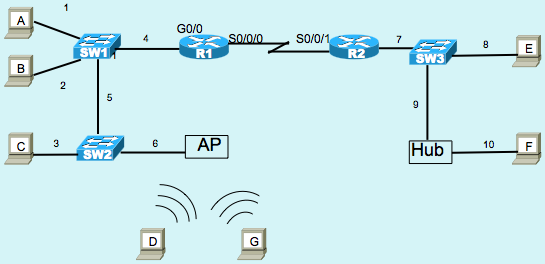
Q: Ethernet Cabling Pinouts
#CCENT test takers sometimes struggle with going from the basic idea of a crossover cable, to looking at a network diagram and deciding which types of cable pinouts to use for each link. Today’s post adds to the practice. As usual, feel free to comment, but I’ll defer comment yes/no about your answer until the answer post is up (which will be linked at the bottom of this post). Thanks!
Question

The Figure shows a small network, with several types of devices. The network has all the correct cabling installed, and the correct configuration, so that all the PCs in the figure can communicate, as proven by their ability to successfully ping each other.
The numbers in the figure simply provide a way for the questions to reference the various parts of the figure. Use the information above when answering the following question:
Question: Each answer lists two links based on the reference numbers in the figure. Which answers list at least one link number for a link that should use crossover cabling pinouts?
A. 1, 2
B. 3, 4
C. 5, 6
D. 7, 8
E. 9, 10

Looking at this figure I’d say that a crossover cable is needed for the switch-to-switch connection. Also, the one I’m not sure of, is the switch-to-hub connection. I think that would require a crossover as well.
Jason,
Your instincts were right – hubs act like switches in regards to Ethernet pinouts. I’ve posted the longer answer in the blog just a few minutes ago, but your comment nails the important part of the analysis. Thanks for joining in…
Wendell
E
Because Hubs & switches use the the same pins 3 & 6 as transmitter and 1,2 as receiver.
NIC, Routers and AP All transmit on PINS 1,2 and Switches and HUBs transmit on 3, 6. so acording to the figure it it link 5 and 9 hat need crossover cables.
Hi Wendell,
If PC transmits on Pins 1&2 and Hubs transmits on Pins 3 & 6, how does the collision happen?
Wish you Happy New Year 2019.
Thank you
Thanks Siva! Happy new year to you, too.
If you ‘ve got the books, read the the first part of chapter 10 in the ICND1 Official Cert Guide, and specifically figure 10-2 and surrounding text.
If not, short versions:
1) Hub receives two frames at the same time. Both signals are repeated out all other ports. So on a 3rd port, the two repeated signals overlap when transmitted on that ports 1,2 pair.
2) Hub uses circuitry to detect the concurrent transmission and receipt of signals on the hubs transmit and receive pairs (called a loopback circuit), just so the hub can tell when a port experiences the case of both transmitting and receiving at the same time. (I don’t bother to show that one in the book any longer, by the way.)
Hope this helps,
Wendell
The Ans. is C & E as both list atleast one segment that uses crossover cable. Link numbered 5 will have to use crossover cable as it connects two like devices(switches). also, the hub and the switch both transmit using pair at pins 3&6 and receive using pair at pins 1&2. so the network engineer will have to use crossover cable connection to connect both the links.
The answer is C.
Two like, devices connect to each other by cross-over cable.
SW1, and, SW2.
SW2, and, AP.
In the answers the choice E, link 9 is Ok, but link 10 is not crossover, but an straight-through cable. Hub transmits on its pins 3, 6, but the PC transmits on its pins 1, 2.
Yeah you are rightm but the wording said “at least one link number that should use crossover cable that in fact was the link 9 between sw and hub.
The answer is C and E.
– C(5) –> SW1 – SW2
– E(9) –> SW3 – Hub