Config Lab: Switch Admin Config
Today’s topic: A lot of administrative settings on a switch, particularly access passwords, that you need to set up when you first install a switch. Enjoy!

The Lab Exercise
Lab Requirements
This lab uses two LAN switches, connected by a link, with a router on the side.
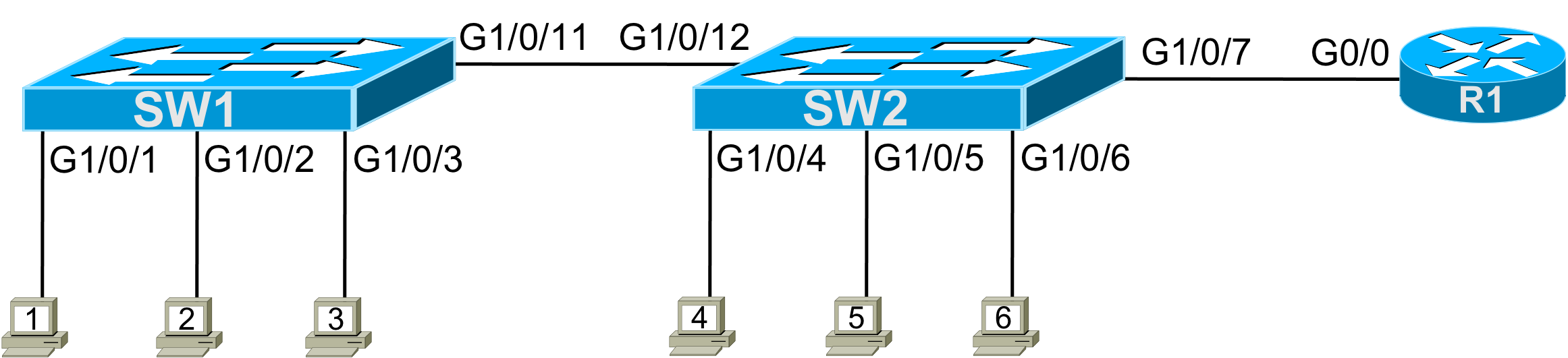
Figure 1 – Lab Topology
For this lab, you need to configure passwords, plus a few other administrative settings. Note that this lab does not ask you to configure IP addressing, leaving that to other labs. However, this lab does ask you to configure the rest of the settings to prepare to allow for inbound Telnet and SSH into the switches.
The requirements are as follows.
- On both switches, protect the console using the password “fred”.
- On switch SW1, allow telnet but not SSH into the switch, with simple password protection without using a username. Use password “sw1”.
- On switch SW2, allow both telnet and SSH into the switch, with both a username and password. You can choose the actual username and password.
- On both SW1 and SW2, do not yet configure IP details; defer that work until the router folks tell you what IP addresses to use.
- Give each switch a hostname to match the figure.
- For each interface used in the lab, document the device’s name on the other end of the link connected to the interface. For instance, for SW1, port G1/0/1, document that “PC1” is on the other end of the link.
- On switch SW1, protect privileged mode using the older style (and easier to break) password. Make this password “sw1bad”.
- On switch SW2, protect privileged mode using the newer style (and more secure) password that uses MD5 encoding. Make this password “sw2good”.
Initial Configuration
This lab begins with a pretty clean slate. Here are the notes for the initial state:
- The router has been configured already and is working.
- The router is connected to other links, not shown; those links are completely unimportant to the lab.
- The two LAN switches have no configuration; just before this lab, their config was erased, and the switches were reloaded.
- This lab avoids VLAN and VLAN trunk topics to keep the focus on passwords and Telnet/SSH. So, the link between the two switches is not a VLAN trunk, and only the default VLAN (VLAN 1) is in use.
Answer Options - Click Tabs to Reveal
You can learn a lot and strengthen real learning of the topics by creating the configuration – even without a router or switch CLI. In fact, these labs were originally built to be used solely as a paper exercise!
To answer, just think about the lab. Refer to your primary learning material for CCNA, your notes, and create the configuration on paper or in a text editor. Then check your answer versus the answer post, which is linked at the bottom of the lab, just above the comments section.
You can also implement the lab using the Cisco Packet Tracer network simulator. With this option, you use Cisco’s free Packet Tracer simulator. You open a file that begins with the initial configuration already loaded. Then you implement your configuration and test to determine if it met the requirements of the lab.
(Use this link for more information about Cisco Packet Tracer.)
Use this workflow to do the labs in Cisco Packet Tracer:
- Download the .pkt file linked below.
- Open the .pkt file, creating a working lab with the same topology and interfaces as the lab exercise.
- Add your planned configuration to the lab.
- Test the configuration using some of the suggestions below.
You can also implement the lab using Cisco Modeling Labs – Personal (CML-P). CML-P (or simply CML) replaced Cisco Virtual Internet Routing Lab (VIRL) software in 2020, in effect serving as VIRL Version 2.
If you prefer to use CML, use a similar workflow as you would use if using Cisco Packet Tracer, as follows:
- Download the CML file (filetype .yaml) linked below.
- Import the lab’s CML file into CML and then start the lab.
- Compare the lab topology and interface IDs to this lab, as they may differ (more detail below).
- Add your planned configuration to the lab.
- Test the configuration using some of the suggestions below.
Network Device Info:
This table lists the interfaces listed in the lab exercise documentation versus those used in the sample CML file.
| Device | Lab Port | CML Port |
| SW1 | G1/0/1 | G2/1 |
| SW1 | G1/0/2 | G2/2 |
| SW1 | G1/0/3 | G2/3 |
| SW1 | G1/0/11 | G1/1 |
| SW2 | G1/0/4 | G3/1 |
| SW2 | G1/0/5 | G3/2 |
| SW2 | G1/0/6 | G3/3 |
| SW2 | G1/0/7 | G0/1 |
| SW2 | G1/0/12 | G1/2 |
Lab Answers Below: Spoiler Alert
Lab Answers: Configuration (Click Tab to Reveal)
Answers: Switch Admin Config
The answers require that you exercise your memory more than performing detailed analysis. Examples 1 and 2 list the answers. The examples list the commands in the same order that IOS would list them in the output of a show running-config command, rather than in the same order as the requirements listed in the original post. To help you navigate the configuration, the examples include comments that reference the requirement number. Figure 1 repeats the figure for reference.
Figure 1 – Lab Topology
! Requirement #5 next
!
hostname SW1

! Requirement #7 below
!
enable password sw1bad

! Requirement #6 next
!

interface GigabitEthernet1/0/1
 description connected to PC1
!
interface GigabitEthernet1/0/2
 description connected to PC2
!
interface GigabitEthernet1/0/3
 description connected to PC3
!
interface GigabitEthernet1/0/11
 description connected to SW2

! Requirement #1 below
line con 0
 password fred
 login

! Requirement #2 below
!
line vty 0 15
 password sw1
 login
 transport input telnet
Example 1: SW1 Config
! Requirement #5 next
!
hostname SW2

! Part of Requirement #3 next; more at the bottom
!
ip domain-name example.com
crypto key generate rsa
username fred password barney

! Requirement #8 below
!
enable secret sw2good

! Requirement #6 next
!

interface GigabitEthernet1/0/4
 description connected to PC4
!
interface GigabitEthernet1/0/5
 description connected to PC5
!
interface GigabitEthernet1/0/6
 description connected to PC6
!
interface GigabitEthernet1/0/12
 description connected to SW1
!
interface GigabitEthernet1/0/7
 description connected to R1

! Requirement #1 below
line con 0
 password fred
 login

! Requirement 3 below; more at the top
!
line vty 0 15
 login local
 transport input telnet ssh
Example 2: SW2 Config
Commentary, Issues, and Verification Tips (Click Tabs to Reveal)
Most of the parameters for the commands in this lab require no analysis – you just need to remember them all. The trickiest part may be remembering all the pieces of the SSH configuration on SW2.
The lab requirements list the need for SSH on SW2 as requirement #3. Let me make a couple of comments about that particular requirement, as follows:
- The requirements did not spell out the username/password pair to use, so any pair you made up is legal. I used fred/barney.
- The requirements did not spell out what domain name to configure; any name you used is fine. I used example.com.
- The default setting on the transport input command in switches (transport input all) works, but I added the transport input all command as a reminder to think about it.
Known Issues in this Lab
This section of each Config Lab Answers post hopes to help with those issues by listing any known issues with Packet Tracer related to this lab. In this case, the issues are:
| # | Summary | Detail |
| 1 | show interfaces status incorrect | This command, in real switches, lists the contents of the description interface subcommand under the heading “name”. PT lists blanks, ignoring the description setting. |
| 2 | show interfaces description not supported | This command, in real devices, lists interfaces and the contents of the description interface subcommand. PT does not support the command. |
| 3 | transport input telnet ssh not supported | This command, in real devices, enables support for both Telnet and SSH in vty line mode. PT does not support the command. Use the transport input all command instead. |
Why Would Cisco Packet Tracer Have Issues?
(Note: The below text is the same in every Config Lab.)
Cisco Packet Tracer (CPT) simulates Cisco routers and switches. However, CPT does not run the same software that runs in real Cisco routers and switches. Instead, developers wrote CPT to predict the output a real router or switch would display given the same topology and configuration – but without performing all the same tasks, an actual device has to do. On a positive note, CPT requires far less CPU and RAM than a lab full of devices so that you can run CPT on your computer as an app. In addition, simulators like CPT help you learn about the Cisco router/switch user interface – the Command Line Interface (CLI) – without having to own real devices.
CPT can have issues compared to real devices because CPT does not run the same software as Cisco devices. CPT does not support all commands or parameters of a command. CPT may supply output from a command that differs in some ways from what an actual device would give. Those differences can be a problem for anyone learning networking technology because you may not have experience with that technology on real gear – so you may not notice the differences. So this section lists differences and issues that we have seen when using CPT to do this lab.
Beyond comparing your answers to this lab’s Answers post, you can test in Cisco Packet Tracer (CPT) or Cisco Modeling Labs (CML). In fact, you can and should explore the lab once configured. For this lab, once you have completed the configuration, try these verification steps.
- You can test the console and enable passwords on switch SW1 from the console, as follows:
- Connect to the console of your SW1. (If already connected, connect and reconnect. Note that the exit command logs you out of the console.)
- Press enter to (hopefully) cause a password prompt to appear.
- Type the console password you just configured to test. You should reach user mode.
- From user mode, issue the enable command; a password prompt should appear.
- Type the enable password and press enter to test whether you configured the enable password correctly.
- Use the same steps to test the console and enable passwords for switch SW2.
- Because this lab did not have configured IP addresses, you cannot test Telnet and SSH into the switches with only the requested configuration. However, use these steps to add enough IP configuration to test from switch SW1, which should be configured to support Telnet but not SSH.
- From switch SW1, enter configuration mode, and add these two commands: interface loopback 1 and ip address 1.1.1.1 255.255.255.0.
- Exit configuration mode.
- Test Telnet into that same switch with the telnet 1.1.1.1 command. If it works, you will see a password prompt, at which you should type the Telnet (vty) password you configured for this lab.
- For switch SW2, test Telnet and SSH with these similar steps:
- Configure a loopback 1 interface but with address 1.1.1.2.
- Test Telnet from the SW2 console with the telnet 1.1.1.2 command.
- To test SSH, use the ssh -l username 1.1.1.2 command, where username is the username you configured in this lab. You should see a password prompt, at which you should type the password you added to the username command.