CCNA Deep Dive:
Cisco CLI and Packet Tracer Basics
Lab 4: Building New Topologies in Packet Tracer
There is NO .PKT FILE for this lab. Instead, you build a new .PKT file based on the lab instructions.
Lab 4 Introduction
The CCNA Deep Dive series labs typically begin with a pre-supplied PT file which has a pre-built topology and initial device configurations. In this lab, you will take a few moments to learn more about how to build your own lab topologies in PT.
Part A: Create a New PT Topology with Minimal Features – In part A of this lab, you should use PT to create a new lab topology. The topology should use the device types, cable types, and interface IDs shown in Figure 4A-1. Note that in Part A, the steps happen to use devices and choices that require almost no extra work – letting you quickly create a new PT Topology.
Part B: Create a New PT Topology with More Features – As in part A, you will create a new topology in PT. However, part B uses choices that require more work – some of which may not be obvious at first. Also, the devices used in this design exercise happen to be the devices you will be more likely to want to use as you move further into your CCNA study. So, take the time to learn the nuances of how to add these devices to a PT design.
Bonus: Create a New PT Topology Using Copy/Paste – The bonus lab section creates a bit of a puzzle. The design shows eight switches and three routers – but then asks you to drag-and-drop only one switch and one router to the PT topology design window. To complete the design, you must use PTs copy/paste features to replicate devices. For extra challenge, think through the process to decide the least number of steps you would need to create the entire design.
Lab 4 Part A: Create a new PT topology to match Figure 4A-1
In part A of this lab, you should use PT to create a new lab topology. The topology should use the device types, cable types, and interface IDs shown in Figure 4-A-1. The rest of the instructions provide the specifics, but you can ignore the steps and just re-create the topology, as shown in the figure.
In this Lab Part, you will take these steps:
A.1 Create a New Lab Topology to Match Figure 4A-1
A.2 Connect Cables to the Devices to Match the Figure
A.3 Confirm Your Topology, Cables, and Interfaces Match the Planning Figure
Figure 4A-1 Lab Topology for Lab 4 Part A

A.1 Create a New PT Topology to Match Figure 4A-1
Add the correct device types to the new topology and assign the correct names:
- From the PT user interface menu, use .. New to create a new blank topology canvas.
- Using the bottom toolbar, arrange the six devices shown in Figure 4A-1.
- For routers, use model 2911.
- For switches, use model 2960.
- For endpoint devices, use a PC.
- Click on the default names for each device (just under each icon) to edit the device name. Rename the device names to match Figure 4A-1.
A.2 Connect Cables to the Devices to Match the Figure
At this point, you should have a topology with the same devices and names as figure 4A-1. Now add cables to match the figure.
- Using the bottom toolbar, select the cable tool to add cables.
- Still in the bottom toolbar, select the specific cable types:
- Black unbroken line – UTP straight-through cable
- Black dashed line – UTP crossover cable
- Orange continuous line – fiber cable
- Add Ethernet cables to match Figure 4A-1. For this scenario, the links use straight-through UTP cables, with one exception: the router-router link uses a UTP crossover cable.
- If you add a cable and need to remove it:
- From the top menu, click the delete tool so that future clicks in the topology area will delete an item.
- Click the cable that you want to delete in the topology to delete the cable.
- In the upper toolbar, click the select tool to re-enable the default mouse behavior of selecting an item.
- Use this reference for the icons used in this section.

Figure 4A-2 Icons Useful for Cabling in PT
A.3 Confirm Your Topology, Cables, and Interfaces Match the Planning Figure
Confirm that the interfaces you used match Figure 4A-1 by using the PT user interface. To do so:
- If still using default preference settings, the PT user interface should list the interface IDs already. Compare those values to Figure 4-A-1. (If the interface IDs do not appear, move the mouse pointer to a cable and hover – the interface IDs should appear.)
- Once completed, get into PT preferences and disable the options for:
- Show device model labels
- Always show port labels in Logical Workspace
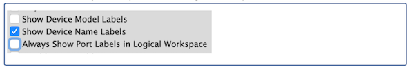
Figure 4A-3 Icons Useful for Cabling in PT
- Verify the interface IDs again by hovering over each cable.
- Save your new topology file with any name you choose. Store it in the /working directory.
Lab 4 Part B: Create a new PT topology to match Figure 4B-1
In part B, you will create another topology – this time requiring you to do a little more work with the devices. As with part A, you should create a new lab topology matching the device types, cable types, and interface IDs shown in Figure 4B-1. The rest of the instructions provide the specifics, but you can ignore the steps and just re-create the topology, as shown in the figure.
In this Lab Part, you will take these steps:
B.1 Create a New PT Topology to Match Figure 4B-1
B.2 Connect a Cable from Each PC to a LAN Switch
B.3 Connect a Cable from Each Switch to a Router
B.4 Connect a Cable between the Routers
B.5 Add a Power Supply to the Switches

Figure 4B-1 Lab Topology for Lab 4 Part B
B.1 Create a New PT Topology to Match Figure 4B-1
Add the correct device types to the new topology and assign the correct names:
- From the PT user interface menu, use .. New to create a new blank topology canvas.
- Using the bottom toolbar, arrange the six devices shown in Figure 4B-1. Do not connect the cables yet.
- For routers, use model 2911.
- For switches, use model 3650-24PS.
- Use endpoint devices, use a PC.
- Click on the default names for each device (just under each icon) to edit the device name. Rename the device names to match Figure 4B-1.
B.2 Connect a cable from Each PC to a LAN Switch
At this point, you should have a topology with the same devices and names as figure 4B-1. Now add cables to match the figure.
- Using the bottom toolbar, select the cable tool to add cables, and choose a straight-through UTP cable type.
- Click PC1, then SW1, to add the cable.
B.3 Connect a Cable from Each Switch to a Router
Connect a cable from each LAN switch to the nearby router, using the ports in Figure 4B-2 – and discover the need for more hardware.
- From the main PT app window, using the bottom toolbar, select the cable tool to add cables, and choose a straight-through UTP cable type.
- Note that per Figure 4B-1, switches SW1 and SW2 should each use their respective G1/1/1 interface to connect to the nearby router’s G0/0 port.
- Note the absence of interface G1/1/1 from the drop-down list on the switch. That occurs because the switch model, 3650, has a G1/1/1 port, but the device cannot use the port until you place an SFP into the port. You have to add the SFP in Packet Tracer.
- From the main PT app window, in the top menu, click the select tool, and then click the SW1 icon to open the detail window for SW1.
- In the physical tab, zoom in, and look to the right. You should see four ports that can accept an SFP.
- In this case, you should drag-and-drop a GLC-T SFP from the far left over to the port for G1/1/1. (If unsure, experiment – you can’t break anything!)
- Go back to the main PT window (to see the topology), and using the cabling options, again attempt to connect a cable from SW1 to router R1. You should now see G1/1/1 as an option from the drop-down menu on SW1.
- Also, connect switch SW2 to router R2.
B.4 Connect a Cable between the Routers
The two routers use a fiber Ethernet link to create the equivalent of an Ethernet WAN service. Next, you will discover the need for more router hardware before connecting the fiber cable between the routers.
- From the main PT app window, using the icons in the bottom menu, attempt to add a fiber cable between the two routers, using the interface IDs listed in Figure 4B-1. Note that the pull-down menus on both routers do not happen to include the correct interfaces.
- From the PT top icon menu, click the select tool, and then click the R1 icon to open the detail window for router R1.
- In the R1 detail window, click to move to the physical tab.
- Make the R1 detail window wide, and then zoom in on the image of the router. Look across the top, and you should see four open WAN Interface Card (WIC) slots.
- If you have excellent eyesight, you might be able to make out the numbers above each slot. Regardless, know that in a 2911, slot 0 is on the right, with the slots numbered right-to-left as 0, 1, 2, and 3.
- Still in the router R1 detail window, physical tab, drag-and-drop the HWIC-1GE-SFP device over to slot 1 (which will create port G0/1/0.) (If PT complains that the router must be powered off, first click the on/off switch in the graphic of the router, and try to add the WIC again.)
- Then drag-and-drop a GLH-LH-SMD – a GBIC – on top of the WIC you just added to slot 1. Doing so is the equivalent of inserting a GBIC into the WIC.
- For good housekeeping, drag-and-drop (three times) the WIC cover to each of the three open slots.
- Power on the router by clicking the on/off switch.
- Repeat this process on router R2, but adding the WIC to slot 2, which will create a G0/2/0 interface on R2.
- Navigate back to the main PT window that shows the topology. Again attempt to connect a fiber cable from R1 to R2; you should now see interface G0/1/0 on R1 and G0/2/0 on R2 in their respective drop-down menus.
B.5 Add a Power Supply to the Switches
The 2911 routers in PT come with a pre-installed power supply, but the 3650-24PS switches leave the power supply slot empty. In real life, you have useful choices to make between different switch power supplies. In PT, you just need to add the one available power supply so that PT will allow each switch to power on. To do so:
- Inside the PT main window, in the top icon trays, click the select tool, and then click the R1 icon to open the detail window for R1
- From R1’s detail window, click the CLI tab, click into the middle of the window and then press enter. Do you get any response at all? ______________________
- Follow the same process to reach the CLI of device SW1. When you press enter within the CLI area for SW1, do you get any response? ___________________
By now, you have seen the message that tells you that the switch should be powered on. As it turns out, the 3650 switch used in this lab has two power supply slots, neither of which has a power supply by default. You just have to add one.
- From the detail window for switch SW1, click to navigate to the physical tab. Zoom in and look to the bottom right. You should see two open slots for power supplies.
- On the far left, you should see a list of the optional hardware you can choose to add to the switch. Drag-and-drop the AC power supply to either open power supply slot.
- On the far left, drag-and-drop the power supply cover, to the other slot (for good housekeeping).
- Click into the CLI tab within this detail window for SW1, click in the middle of the window, and press enter a few times. Does the CLI window respond? Does it behave differently now? __________________________________
Lab 4 Bonus: Create a new PT topology to match Figure 4C-1
The Bonus section provides a little additional learning for those moving quickly through the lab. If you do not reach this section, do not be concerned. This bonus section gives you a little general guidance, expecting you to experiment and ask questions during class as needed.
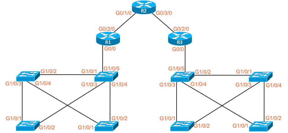
Figure 4C-1 Lab Topology for Lab 4 Bonus
Create a New PT Topology to Match Figure 4C-1
For the bonus section, you should create yet another topology – but this time with some rules that force you to learn some other cool PT features. Specifically:
- Create a new topology like Figure 4C-1.
- You may drag-and-drop only two devices from the bottom menu:
- One 3650-24PS switch
- One 2911 router
- To create the rest of the devices in the topology, you must use PT’s copy/paste features.
- Challenge yourself: What is the most efficient process you could have used to save time to make this topology? (Describe it out in the group chat or QA window).